Detect Events from GPIO Data
This tool uses 0.5 compute credits per hour.
Overview
A General Purpose Input Output (GPIO) file contains information about important events (coded as
pulses or step-signal transitions) that were monitored during the experimental recording. The Detect GPIO events
tool extracts the timestamps of the events from the specified channel in the GPIO file.
Parameters
| Parameter | Required? | Default | Description |
|---|---|---|---|
| Input File | True | N/A | path to the input file |
| GPIO Channel Name | True | GPIO-1 | Channel for which the events are to be extracted |
| Pulse threshold | True | 0 | Fraction of the max signal value to use as the pulse threshold. |
| Event Type | True | onset | Define event time as either a pulse onset or a pulse offset |
Input File
The input to this tool consists of a single GPIO file that contains either analog or logical data originally recorded with a nVoke/nVista DAQ box.
| Source Parameter | File Type | File Format |
|---|---|---|
| Input File | gpio_traces, gpio_data | gpio, gpio |
GPIO Channel
Events can be extracted from one of the following GPIO channels:
- Digital GPI 0...7
- Digital GPO 0...7
- GPIO-1...4
- EX-LED, EX-LED1 or EX-LED2
- OG-LED
- DI-LED
- e-focus
- BNC Sync Output
- BNC Trigger Input
Event Type
An event can be defined as the time at which a pulse onset or an offset is encountered. Choose either
onset or offset to define which aspect of a pulse an event corresponds to.
Output Data
The output of this tool is a h5 events file that contains the timestamps of the events
detected on the specified GPIO channel.
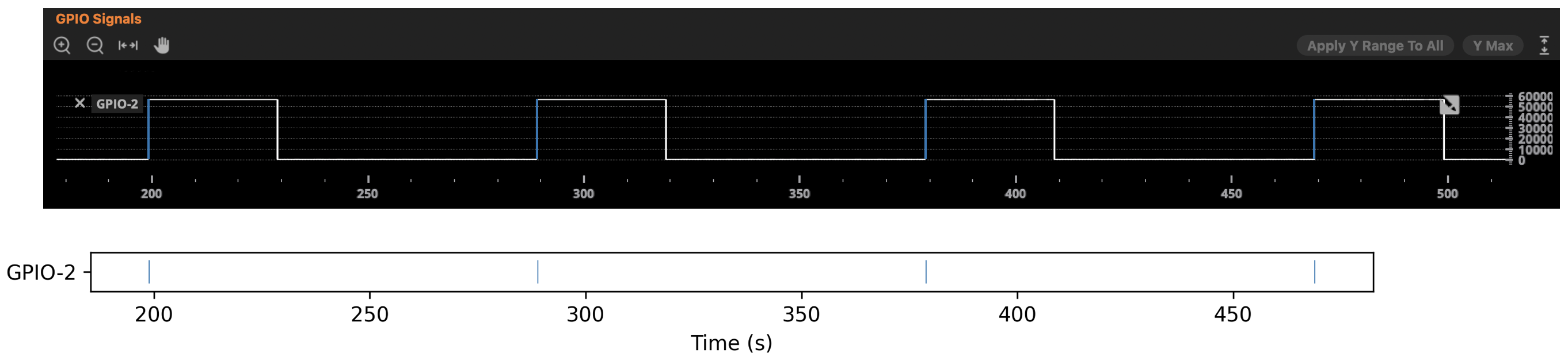
The diagram below illustrates the events detected on channel GPIO-2 of a given GPIO file.
The input pulses are visualized in the Inscopix Data Processing Software in the top panel.
The bottom panel shows the corresponding events extracted from this channel when
identifying event times based on pulse onsets.
Next Steps
After running this tool, the output events file can be used as input to the Peri-Event Analysis Workflow tool.